Cooling system
GEMCO-C reverse-flow type pellet cooler is kind of a pendulum layout cooler, mainly used in the process of pellet cooling in pellet plants.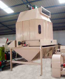
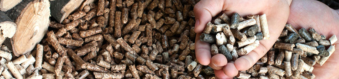
Pellets after cooled will become harder and more stabilized for easy transportation and storage. The pellet cooler is also applied to dust material or big diameter material.
As of now, the reverse-flow pellet cooling machine, as one of the latest coolers prevailing across the globe, avails itself of the counter flow cooling theory to refrigerate granules with high temp and moisture, namely, when vertically passing through the bed of material, the cold air will sweep through cold material. And then the increasingly warm-up air will diffuse together with hot material yet the air direction is opposite to the material flow, hence, granules will be cooled gradually and forwardly lest other wood pellet coolers directly shock-chill the high-temp material and the surface of granules thereby crazes. Because the cold air goes into the wood pellet cooling machine in all direction covering large area and in high-use, therefore, the cooling effect goes outstanding. Also, thanks to its low energy consumption and convenient operation, this type of cooler precedes over even updated vertical and horizontal types.
Technical parameters
| Model | Capacity(m3) | Cooling time(min) | Water reducing ratio | Final Temp℃ | Motor for discharge(kw) | Motor for feeding(kw) |
| 19×19 | 4.6 |
Not less than 10~15min |
≥3~3.5% | RT+3~5 | 1.1 | 1.1 |
| 24×19 | 5.25 | 1.1 | 1.1 | |||
| 24×24 | 7.5 | 1.5 | 1.5 | |||
| 28×28 | 11.2 | 1.1 | 2.2 | |||
| 28×38 | 13 | 1.1 | 2.2 |
Main Structures and Operating Principles
The structure of the cooler shall be referred to drawing 1. The cooler mainly consists of air seal machine, induced draft cover, cooling chamber, both upper and lower material level indicators, reducer, framework and aggregate bin. The working process remains as follows: high-temp and high moisture granules produced from the pellet mill will be piled up in the cooling chamber by passing through air seal machine and material discharger in turn. Cold air through the cooling chamber will enter into the cooler, and its heat exchange with damp and hot granules will take place after the cold air going through the bed of material. Then, granules will get cooled after the work of induced draft system. Cool-down time depends on positions of both upper and lower material level indicators, that is, when the level of material reaches to the upper, material discharge will be driven by motor and vice versa. The cooled granules will be discharged out through the aggregate bin.
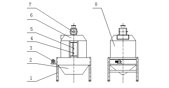
The structure diagram
1. framework 2. aggregate bin 3. reducer 4. lower material level indicator 5. upper material level indicator 6. air seal machine 7. induced draft cover 8. cooling chamber